Showing posts with label Tech. Show all posts
thumbnail

Anti-lag system

An anti-lag system (ALS) or misfiring system is a system used on turbocharged engines to minimize turbo lag on racing cars. It works by arranging for fuel and air to be in the exhaust duct after the engine, and before the turbocharger. This ignites in the hot ducting and the combustion process that occurs there keeps the turbocharger spinning when the engine is not delivering enough exhaust gas.

Overview:
ALS was first used in the early days of turbocharged cars in Formula One racing circa mid to late 1980s, until fuel restrictions made its use unsuitable. Later it became a common feature in rally cars because of the increased turbo lag from the mandated restrictors at the intake manifold inlet. Due to the pressure drop across the restriction, the pressure ratio for a given boost level is much higher and the turbocharger must spin much faster to produce the same boost as when the engine operates without restriction. This increases turbo lag significantly compared to unrestricted turbochargers.
An ALS requires an air bypass, generally done in one of two ways. The first method is to use a throttle air bypass; this may be an external bypass valve or a solenoid valve which opens the throttle 12-20 degrees. This allows air to bypass the closed throttle and to reach the engine. The second method is to use a bypass valve which feeds charge air directly to the exhaust manifold.

Methods:
Throttle bypass, or throttle kick ALS:
The throttle bypass/throttle solenoid system is combined with ignition retardation and slight fuel enrichment (mainly to provide cooling), typically ignition occurs at 35-45° ATDC. This late ignition causes very little expansion of the gas in the cylinder; hence the pressure and temperature will still be very high when the exhaust valve opens. At the same time, the amount of torque delivered to the crankshaft will be very small (just enough to keep the engine running). The higher exhaust pressure and temperature combined with the increased mass flow is enough to keep the turbocharger spinning at high speed thus reducing lag. When the throttle is opened up again the ignition and fuel injection goes back to normal operation. Since many engine components are exposed to very high temperatures during ALS operation and also high pressure pulses, this kind of system is very hard on the engine and turbocharger. For the latter not only the high temperatures are a problem but also the uncontrolled turbo speeds which can quickly destroy the turbocharger. In most applications the ALS is automatically shut down when the coolant reaches a temperature of 110–115 °C to prevent overheating.

Secondary air injection, or inlet bypass:
An ALS working with a bypass valve which feeds air directly to the exhaust system can be made more refined than the system described above. Some of the earliest systems of this type were used by Ferrari in F1. Another well-known application of this type of anti-lag system was in the WRC version of the 1995 Mitsubishi Lancer Evolution III and Toyota Celica GT-Four (ST205). Brass tubes fed air from the turbocharger's Compressor Bypass Valve (CBV) to each of the exhaust manifold tracts, in order to provide the necessary air for the combustion of the fuel. The system was controlled by two pressure valves, operated by the ECU. Besides the racing version, the hardware of the anti-lag system was also installed in the 2500 "Group A homologation base WRC method car" street legal Celica GT-Fours. However, in these cars the system was disabled and inactive. The tubes and valves were only present for homologation reasons. On the Mitsubishi Evolution later series (evo 4-9, JDM models only) the SAS (Secondary Air System) can be activated to provide Antilag. Mitsubishi Antilag system diagram Secondary air injection ALS

Turbo and intercooler bypass (D-valve):
A method by which a large one-way check valve is inserted just prior to the throttle body, enabling air to bypass the turbo, intercooler, and piping during periods where there is negative air pressure at the throttle body inlet. This results in more air combusting, which means more air driving the turbine side of the turbo. As soon as positive pressure is reached in the intercooler hosing, the valve closes.
Sometimes referred to as the Dan Culkin valve.
When used in a MAF configuration, the D-valve should draw air through the MAF to maintain proper A/F ratios. This is not necessary in a speed-density configuration.

Two-step anti-lag/launch control:
A method of anti-lag developed along the same technique previously mentioned, but designed only to allow reduction of turbo lag when a car is initially pulling away from a standing start. These systems can be integrated into the engine management or existing anti-lag system, or can be fitted as a standalone unit. The basic method of operation is to artificially lower the engine rev limiter to hold the engine at a speed where the turbo can produce usable boost, by altering the ignition. Because the ignition is alternately cut or retarded, there is similar noise and misfires associated with other anti-lag systems. Systems for two-step launch designed to be fitted in addition to the existing engine management work by interrupting the crank position sensor signal, so that the engine develops a controlled misfire at a pre-determined RPM. The basic premise of the launch control system is to build positive boost pressure from a static engine, releasing full or increased power to the wheels when the car starts to move off. It is most commonly used in turbocharged drag cars, primarily in the US, Australia, Puerto Rico and Japan, although most WRC cars utilise launch control to ensure that the cars can get off the line much more quickly.

Usage:
Today's WRC cars also use anti-lag systems which feed air directly to the exhaust system. The reason is that these systems are more refined, more effective with advanced computer control, and also quieter. Today this kind of system has reached such a refinement that it's even possible to use the system in a road car. A recent example is the Prodrive P2 prototype. The system works by bypassing charge air directly to the exhaust manifold which acts as a combustor when fuel rich exhaust from the engine meets up with the fresh air from the bypass. This will provide a continuous combustion limited to the exhaust manifold which significantly reduces the heat and pressure loads on the engine and turbocharger. With the latest anti-lag systems the bypass valve can not only be opened or closed but it can actually control the flow of air to the exhaust manifold very accurately. The turbocharger is fitted with a turbo speed sensor and the engine management system has a map based on throttle position and car speed which is used to find a suitable turbocharger speed and boost pressure for every condition. When the engine alone can’t provide enough exhaust energy to reach the turbo speed/boost demanded by the management system, the bypass valve opens and exhaust manifold combustion begins. This not only reduces turbo load, but it also allows boost to be produced at very low engine speeds where boost was previously limited by compressor surge or exhaust energy. With relatively high boost at low speeds, this makes the low end torque superior even to large naturally aspirated engines. This is loud and has been banned on some rallies because of the noise it produces.


thumbnail

Limited-slip differential (LSD)

A limited-slip differential (LSD) is a type of automotive differential gear arrangement that allows for some difference in angular velocity of the output shafts, but imposes a mechanical limit on the disparity.

In an automobile, such limited-slip differentials are sometimes used in place of a standard differential, where they convey certain dynamic advantages, at the expense of greater complexity.

Early history:
In 1932, Ferdinand Porsche designed a Grand Prix racing car for the Auto Union company. The high power of the design caused one of the rear wheels to experience excessive wheel spin at any speed up to 100 mph (160 km/h). In 1935, Porsche commissioned the engineering firm ZF to design a limited-slip differential to improve performance. The ZF "sliding pins and cams" became available, and one example was the Type B-70 for early VWs.

Benefits:
The main advantage of a limited-slip differential is demonstrated by considering the case of a standard (or "open") differential in off-roading or snow situations where one wheel begins to slip. In such a case with a standard differential, the slipping or non-contacting wheel will receive the majority of the power (in the form of low-torque, high rpm rotation), while the contacting wheel will remain stationary with respect to the ground. The torque transmitted by an open differential will always be equal at both wheels; if one tyre is on a slippery surface, the supplied torque will easily overcome the available traction at a very low number. For example, the right tyre might begin to spin as soon as 50lb-ft of torque is placed on it, since it is on an icy surface. Since the same amount of torque is always felt at both wheels, regardless of the speed which they are turning, this means that the wheel with traction cannot receive more than 50lb-ft of torque either, which is far less than is required to move the vehicle. Meanwhile, the tyre on the slippery surface will simply spin, absorbing all of the actual power output (which is a function of torque provided over time), even though both wheels are provided the same (very low) amount of torque. In this situation, a limited-slip differential prevents excessive power from being allocated to one wheel, and so keeps both wheels in powered rotation, ensuring that the traction will not be limited to the wheel which can handle the minimum amount of power. The advantages of LSD in high-power, rear wheel drive automobiles were demonstrated during the United States "Muscle-Car" era from the mid 1960s through the early 1970s. It soon became apparent that "Muscle-Cars" with LSD or "posi" (positraction) were at a distinct advantage to their wheel-spinning counterparts.

Basic principle of operation:
Automotive limited-slip differentials all contain a few basic elements. First, all have a gear train that, like an open differential, allows the output shafts to spin at different speeds while holding the sum of their speeds proportional to that of the input shaft.

Second, all have some sort of mechanism that applies a torque (internal to the differential) that resists the relative motion of the output shafts. In simple terms, this means they have some mechanism which resists a speed difference between the outputs, by creating a resisting torque between either the two outputs, or the outputs and the differential housing. There are many mechanisms used to create this resisting torque. The type of limited-slip differential typically gets its name from the design of this resisting mechanism. Examples include viscous and clutch-based LSDs. The amount of limiting torque provided by these mechanisms varies by design and is discussed later in the article.

A limited-slip differential has a more complex torque-split and should be considered in the case when the outputs are spinning the same speed and when spinning at different speeds. The torque difference between the two axles is called Trq d . (In this work it is called Trq f for torque friction). Trq d is the difference in torque delivered to the left and right wheel. The magnitude of Trq d comes from the slip-limiting mechanism in the differential and may be a function of input torque (as in the case of a gear differential), or the difference in the output speeds (as in the case of a viscous differential).
The torque delivered to the outputs is:
Trq 1 = ½ Trq in + ½ Trq d for the slower output
Trq 2 = ½ Trq in – ½ Trq d for the faster output

When traveling in a straight line, where one wheel starts to slip (and spin faster than the wheel with traction), torque is reduced to the slipping wheel (Trq 2 ) and provided to the slower wheel (Trq 1 ).
In the case when the vehicle is turning and neither wheel is slipping, the inside wheel will be turning slower than the outside wheel. In this case the inside wheel will receive more torque than the outside wheel, which can result in understeer.

When both wheels are spinning at the same speed, the torque distribution to each wheel is:
Trq (1 or 2) = ½ Trq in ±(½ Trq d ) while
Trq 1 +Trq 2 =Trq in .

This means the maximum torque to either wheel is statically indeterminate but is in the range of ½ Trq in ±( ½ Trq d ).

Types:
-Fixed value
-Torque sensitive
-Speed sensitive
-Electronically controlled

Fixed value:
In this differential the maximum torque difference between the two outputs, Trq d , is a fixed value at all times regardless of torque input to the differential or speed difference between the two outputs. Typically this differential used spring-loaded clutch assemblies.

Torque sensitivity (HLSD):
This type includes helical gear limited-slip differentials and clutch, cone (an alternative type of clutch) where the engagement force of the clutch is a function of the input torque applied to the differential (as the engine applies more torque the clutches grip harder and Trq d increases).

Torque sensing LSDs respond to driveshaft torque, so that the more driveshaft input torque present, the harder the clutches, cones or gears are pressed together, and thus the more closely the drive wheels are coupled to each other. Some include spring loading to provide some small torque so that with little or no input torque (trailing throttle/gearbox in neutral/main clutch depressed) the drive wheels are minimally coupled. The amount of preload (hence static coupling) on the clutches or cones are affected by the general condition (wear) and by how tightly they are loaded.

Clutch, cone-type, or plate LSD:
The clutch type has a stack of thin clutch-discs, half of which are coupled to one of the drive shafts, the other half of which are coupled to the spider gear carrier. The clutch stacks may be present on both drive shafts, or on only one. If on only one, the remaining drive shaft is linked to the clutched drive shaft through the spider gears. In a cone type the clutches are replaced by a pair of cones which are pressed together achieving the same effect.

One method for creating the clamping force is the use of a cam-ramp assembly such as used in a Salisbury/ramp style LSD. The spider gears mount on the pinion cross shaft which rests in angled cutouts forming cammed ramps. The cammed ramps are not necessarily symmetrical. If the ramps are symmetrical, the LSD is 2 way. If they are saw toothed (i.e. one side of the ramp is vertical), the LSD is 1 way. If both sides are sloped, but are asymmetric, the LSD is 1.5 way. (See the discussion of 2, 1.5 and 1 way below)

An alternative is to use the natural separation force of the gear teeth to load the clutch. An example is the center differential of the 2011 Audi Quattro RS 5.

As the input torque of the driveshaft tries to turn the differential center, internal pressure rings (adjoining the clutch stack) are forced sideways by the pinion cross shaft trying to climb the ramp, which compresses the clutch stack. The more the clutch stack is compressed, the more coupled the wheels are. The mating of the vertical ramp (80–85° in practice to avoid chipping) surfaces in a one-way LSD on overrun produces no cam effect or corresponding clutch stack compression.

2-Way, 1-way, 1.5-Way:
Broadly speaking, there are three input torque states: load, no load, and over run. During load conditions, as previously stated, the coupling is proportional to the input torque. With no load, the coupling is reduced to the static coupling. The behavior on over run (particularly sudden throttle release) determines whether the LSD is 1 way, 1.5 way, or 2 way.

A 2-way differential will have the same limiting torque Trq d in both the forward and reverse directions. This means the differential will provide some level of limiting under engine braking.
A 1-way differential will provide its limiting action in only one direction. When torque is applied in the opposite direction it behaves like an open differential. In the case of a FWD car it is argued to be safer than a 2-way differential. The argument is if there is no additional coupling on over run, i.e. a 1-way LSD as soon as the driver lifts the throttle, the LSD unlocks and behaves somewhat like a conventional open differential. This is also the best for FWD cars, as it allows the car to turn in on throttle release, instead of ploughing forward.

A 1.5-way differential refers to one where the forward and reverse limiting torques, Trq d_fwd, d_rev , are different but neither is zero as in the case of the 1-way LSD. This type of differential is common in racing cars where a strong limiting torque can aid stability under engine braking.

Geared LSD:
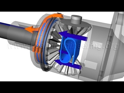
Geared, torque-sensitive mechanical limited-slip differentials use worm gears and spur gears to distribute and differentiate input power between two drive wheels or front and back axles. This is a completely separate design from the most common beveled spider gear designs seen in most automotive applications. As torque is applied to the gears, they are pushed against the walls of the differential housing, creating friction. The friction resists the relative movement of the outputs and creates the limiting torque Trq d .

Unlike other friction-based LSD designs that combine a common spider gear "open" differential in combination with friction materials that inhibit differentiation, the torque sensing design is a unique type of differential, with torque bias inherent to its design, not as an add-on. Torque bias is only applied when needed, and does not inhibit differentiation. The result is a true differential that does not bind up like LSD and locking types, but still gives increased power delivery under many road conditions.

Examples include:
 -Torsen T-1 is the brand name of the original Gleasman Differential invented by Vernon Gleasman circa 1949 (US Patent 2,559,916 applied in 1949, granted 1951). The original Gleasman design was sold to The Gleason Works (later named Gleason Corporation), who started marketing it in 1982. The original T-1 model is incompatible with c-clip drive axles, which limited its use with many cars and trucks of the time. However, the original Torsen differential was used in racing by Mario Andretti and Paul Newman with great success. All later worm gear LSD designs were derived from the original Gleasman differential. The T-1 is original equipment in the Audi Quattro, Subaru Impreza WRX STI, Toyota Mega Cruiser and AM General HMMWV "Humvee".
  -Torsen T-2 was a new Gleasman design circa 1984 (US Patent application WO1984003745 A1) that is compatible with c-clip axles. The new design, along with a merger creating Zexel-Gleason U.S.A. increased Torsen availability for OEM and aftermarket applications. Variants include the T-2R, which includes a Positraction style clutch pack that gives preload for racing purposes; and the T-3, a dual differential intended for AWD applications. The T-2 is original equipment in many high performance cars and trucks.
 -Quaife differential, sold under the name Automatic Torque Biasing Differential (ATB), covered by European Patent No. 130806A2. The Quaife version is most established in Europe and other markets other than the US, providing extensive aftermarket support for European and Japanese brand cars, especially front wheel drive and all-wheel drive applications. The Ford Focus RS uses the Quaife as original equipment.
 -Eaton Corporation is the latest owner of the Truetrac differential, which has been quietly in production for many years. Its design is similar to the Torsen T-2 (slightly less torque bias), and is an aftermarket part for many popular US-made solid axles for rear wheel drive and 4x4 trucks. The Truetrac is most often used in the front axle of 4x4 trucks intended for off-road use, in combination with locking center and rear differentials. As is the case with all geared LSD designs, the Truetrac does not have any negative impact on steering that most other LSD and "locker" designs are prone to,

Speed sensitivity:
Speed-sensitive differentials limit the torque difference between the outputs, Trq d , based on the difference in speed between the two output shafts. Thus for small output speed differences the differential’s behavior may be very close to an open differential. As the speed difference increase the limiting torque increases. This results in different dynamic behavior as compared to a torque sensitive differential.

Viscous (VLSD):
The viscous type is generally simpler because it relies on hydrodynamic friction from fluids with high viscosity. Silicone-based oils are often used. Here, a cylindrical chamber of fluid filled with a stack of perforated discs rotates with the normal motion of the output shafts. The inside surface of the chamber is coupled to one of the driveshafts, and the outside coupled to the differential carrier. Half of the discs are connected to the inner, the other half to the outer, alternating inner/outer in the stack. Differential motion forces the interleaved discs to move through the fluid against each other. In some viscous couplings when speed is maintained the fluid will accumulate heat due to friction. This heat will cause the fluid to expand, and expand the coupler causing the discs to be pulled together resulting in a non-viscous plate to plate friction and a dramatic drop in speed difference. This is known as the hump phenomenon and it allows the side of the coupler to gently lock. In contrast to the mechanical type, the limiting action is much softer and more proportional to the slip, and so is easier to cope with for the average driver. New Process Gear used a viscous coupling of the Ferguson style in several of their transfer cases including those used in the AMC Eagle.

Viscous LSDs are less efficient than mechanical types, that is, they "lose" some power. In particular, any sustained load which overheats the silicone results in sudden permanent loss of the differential effect. They do have the virtue of failing gracefully, reverting to semi-open differential behavior. Typically a visco-differential that has covered 60000 miles (97000 km) or more will be functioning largely as an open differential. The silicone oil is factory sealed in a separate chamber from the gear oil surrounding the rest of the differential. This is not serviceable; when the differential's behavior deteriorates, the VLSD center must be replaced.

Gerotor pump:
This style limited-slip differential works by using a gerotor pump to hydraulically compress a clutch to transfer torque to the wheel that is rotating the slowest. The gerotor pump uses the differential carrier or cage to drive the outer rotor of the pump and one axle shaft to drive the inner rotor. When there is a difference between the left and right wheels' speed, the pump pressurizes the hydraulic fluid causing the clutch to compress. thereby causing the torque to be transferred to the wheel that is rotating the slowest. These pump-based systems have a lower and upper limits on applied pressure which allows the differential to work like a conventional or open differential until there is a significant speed difference between the right and left wheel, and internal damping to avoid hysteresis. The newest gerotor pump based system has computer regulated output for more versatility and no oscillation.

Electronic:
An electronic limited-slip differential will typically have a planetary or bevel gear set similar to that of an open differential and a clutch pack similar to that in a torque sensitive or gerotor pump based differential. In the electronic unit the clamping force on the clutch is controlled externally by a computer or other controller. This allows the control of the differential’s limiting torque, Trq d , to be controlled as part of a total chassis management system. An example of this type of differential is Subaru’s DCCD used in the 2011 Subaru WRX STi. Another example is the Porsche PSD system used on the Porsche 928. A third example is the SAAB XWD (Haldex Generation 4) with eLSD, it uses a common (electronically controlled via the vehicle computer network) hydraulic power pack to control both the longitudinal and transversal torque transfer of the XWD system. The same Haldex system is used on several other GM Epsilon based vehicles such as the Cadillac SRX etc.

Electronic systems: brake-based:
These systems are alternatives to a traditional limited-slip differential. The systems harness various chassis sensors such as speed sensors, anti-lock braking system (ABS) sensors, accelerometers, and microcomputers to electronically monitor wheel slip and vehicle motion. When the chassis control system determines a wheel is slipping, the computer applies the brakes to that wheel. A significant difference between the limited-slip differential systems listed above and this brake-based system, is that brake-based systems do not inherently send the greater torque to the slower wheel, plus the added brake friction material wear that results from the use of such a system if the vehicle is driven in an environment where the brake-based system will activate on a regular basis.

BMW's electronic limited-slip differential used on the F10 5-series is an example of such a system. Another example began on the first year (1992) production of the re-styled, and new 4.6L V-8 overhead cam Ford Crown Victoria model with its optional anti-lock brakes. This option was available on the 1992 Crown Victoria, onward; on those cars equipped with anti-lock brakes.

Other related final drives:
-Spool
-Locking differential

Factory names:
In the 1950s and 1960s many manufacturers began to apply brand names to their LSD units. Packard pioneered the LSD under the brand name "Twin Traction" in 1956, becoming one of the first manufacturers. Other factory names for LSDs include:
Alfa Romeo: Q4, Q2
Audi: Quattro, Quattro with Sport Differential (rear axle)
American Motors: Twin-Grip
BMW: X-Drive, X-Drive with Dynamic Performance Control (rear axle), Active M Differential (FR-based M-models)
Buick: Positive Traction. Gran Sport models used the term "Limited-slip (differential)"
Cadillac: Controlled
Chevrolet/GMC Positraction
Chrysler: Sure Grip
Dana Corporation:Trak-Lok or Powr-Lok
Ferrari: E-Diff
Fiat, Lancia: Viscodrive
Ford: Equa-Lock and Traction-Lok
Hyundai: HTRAC
International: Trak-Lok (clutches only) or Power-Lok (clutch and ramping engagement process)
Jeep: Trac-Lok (clutch-type mechanical), Tru-Lok (gear-type mechanical), and Vari-Lok (gerotor pump), Power Lok
Maserati: Equ-Tor
Oldsmobile: Anti-Spin
Pontiac: Safe-T-Track
Porsche: PSD (electro-hydraulic mechanical), Porsche Torque Vectoring/Plus (PTV/Plus, combined electro-hydraulic mechanical and brake-based type; rear axle only)
Saab: Saab XWD eLSD
Studebaker-Packard Corporation: Twin Traction
Toyota: LSD
TVR: Hydratrak
Yukon Gear & Axle: Duragrip
Mercedes: ASR, AMG Rear-Axle Differential Lock (active differential on select FR-based AMG/S models; pure mechanical variant also present on select non-S AMG models)


ZF LSD
Audi Torsen quattro
thumbnail

Sensotronic Brake Control (SBC)

Sensotronic Brake Control (SBC) is an electro-hydraulic brake system developed by Daimler and Bosch. The SBC system was introduced on the R230 SL-class, which went on sale in Europe in October 2001

How it works:
In a hydraulic brake system, the driver applies force by a mechanical link from the pedal to the master brake cylinder. In turn the master brake cylinder develops hydraulic pressure in the wheels. In contrast, the electro-hydraulic brake SBC provides the brakes with a brake fluid supply from the hydraulic high-pressure reservoir, which is sufficient for several braking events. A piston pump driven by an electric motor supplies a controlled brake fluid pressure between 140 and 160 Bar in the gas diaphragm reservoir.

When the driver presses the brake pedal - or when ESP intervenes to stabilize the vehicle - the SBC control unit calculates the desired target brake pressures on each individual wheel. Through the use of independent pressure modulators the system regulates the hydraulic pressure at each wheel. These four pressure modulators consist of one inlet and one outlet valve, controlled by electronic output stages.

The system employs a travel sensor and a pressure sensor at the pedal to measure the speed and force of the driver's command. The control unit processes this information and generates the control signals for the wheel pressure modulators. Normally, the master brake cylinder is detached from the brake circuit. A pedal travel simulator creates normal pedal feedback. If ESP intervenes, the high-pressure reservoir supplies the required brake pressure quickly and precisely to selected wheels, without any driver involvement.

Advantages and disadvantages:
With fine-grained control of pressure at each wheel, SBC offers a unique platform in which to implement skid protection and traction control compared to cf. Anti-lock braking system (ABS) and Electronic Stability Control (ESC), respectively. Moreover, the system offers innovative functions to reduce the driver's workload. These include Traffic Jam Assist, which brakes the vehicle automatically in stop-and-go traffic once the driver takes his or her foot off the accelerator. The Soft-Stop function - another first - assists with smooth stopping in town traffic.

In case of computer failure, SBC reverts to an hydraulic master cylinder, but driver effort and stopping distance is reported to increase. In case of pump failure the high-pressure reservoir is capable of retaining enough pressure to stop the vehicle electronically. Information on other types of failure remain an open question.

Industry recognition:
In 2001 the µ-Club, an association of international experts in the field of brake technology, honored Robert Bosch GmbH and DaimlerChrysler AG for the development of the electrohydraulic brake SBC. The respective project managers of both enterprises received the award in the form of the µ-medal in Bad Neuenahr.

The Greek letter µ symbolizes in physics the coefficient of friction between two materials. Approximately 350 specialists in the field of brake and safety technology for motor vehicles meet once a year in order to exchange new knowledge. Since 1998, the µ-Club has given awards to persons for the outstanding achievements in their special areas of expertise.

Problems:
In May 2004, Mercedes recalled 680000 vehicles equipped with the system; in March 2005 a total of 1.3 million vehicles were recalled. In 2006 high volume models such as the E-class returned to conventional hydraulic brake systems. Low-volume luxury models such as the SL, the Maybach and the SLR continued to use SBC due to the prohibitive cost of redesign.


thumbnail

How Mercedes Benz BLUETEC Works

BLUETEC is the brand name Mercedes is applying to their new "clean" diesel cars. Let's take a technical tour of the BLUETEC system from engine to tailpipe.

3.0 L ENGINE:
The heart of Mercedes diesel cars like the E 320 BLUETEC is a 3.0 L, V6, turbodiesel engine. The engine has four valves per cylinder and each fuel injector is located at the center of the top of the combustion chamber, in the same location where most four valve gasoline engines locate the spark plug, for optimum fuel burn.

A chain-driven balance shaft inside the engine smoothes out vibration.

COMMON-RAIL INJECTION:
Whereas older diesel engines have a mechanical pump that feeds each cylinder individually, the BLUETEC's injectors are fed by a central fuel rail that is supplied with fuel at extremely high pressure (approx. 23000 psi).

PIEZO INJECTORS:
Diesel combustion is achieved compressing air to raise its temperature and then injecting fuel. The fuel burns and expands, pushing the piston down. Traditional injectors used a mechanical or magnetic valve. The Mercedes engine's individual injectors use piezo-ceramic elements whose crystalline structure changes shape as electric current is applied. The piezo injectors can divide the injection cycle into as many as five separate injection events, each specially timed to maximize combustion efficiency. This not only improves economy and lowers emissions, but it also reduces noise.

EXHAUST TREATMENT:
The BLUETEC system has a number of components that "scrub" the exhaust before it is released into the atmosphere.

Two variants of the BLUETEC system exist: the NAC+SCR system and the AdBlue system. NAC+SCR is used on the "45 state" version of the E320; AdBlue were introduced in the 2008 model year and sold in all 50 states.

NAC+SCR:
Exhaust leaves the engine and passes through a Diesel Oxidation Catalyst (DOC), which reduces carbon monoxide and unburned hydrocarbons in the exhaust.

Next is the NOx Absorber Catalyst, or NAC, which removes and traps oxides of nitrogen (NOx is one of the chief elements in diesel pollution). During periods of lean operation (low fuel-to-air ratio) NOx is stored; under richer operating conditions (which can be created by manipulating the fuel injection) the NAC undergoes a regeneration process and releases ammonia into the exhaust. The ammonia is stored downstream in the Selective Catalytic Reduction (SCR) catalyst which uses it to further reduce NOx.

In between the NAC and SCR catalysts is a particulate filter that traps particulate emissions (soot). As the particulate filter becomes full, the engine computer manipulates the fuel injection process to raise the exhaust gas temperature, which in turn burns off the particulates.

ADBLUE:
The AdBlue system houses the DOC and particulate filter in a single housing. In addition to the NAC catalyst, ammonia is supplied by injecting a fluid called AdBlue into the exhaust upstream of the SCR catalyst. The addition of AdBlue fluid enables the SCR catalyst to reduce NOx emissions to a level even lower than the NAC-SCR system. AdBlue is carried in an on-board tank which can be replenished when the car is serviced; a gallon of AdBlue fluid lasts approximately 3860 km (2400 miles)

.


thumbnail

Blind spot monitor

The blind spot monitor is a vehicle based sensor device that detects other vehicles located to the driver’s side and rear. Warnings can be visual, audible, vibrating or tactile.

However, blind spot monitors are an option that may include more than monitoring the sides of the vehicle. It can include "Cross Traffic Alert," "which alerts drivers backing out of a parking space when traffic is approaching from the sides."

History:
If side view mirrors are properly adjusted in a car, there is no blind spot on the sides. This method was first revealed by George Platzer in a 1995 paper presented to the Society of Automotive Engineers. The method is frequently overlooked in Driver's education classes, and takes some getting used to. Calculated elimination of blind spots by trained drivers is cheap, and obviates the need for expensive technological solutions to that problem, provided drivers take the time to set up and use their mirrors properly.

George Platzer received a patent for the blind spot monitor, and it has been incorporated into various products associated with Ford Motor Company. The blind zone mirror has been touted as "an elegant and relatively inexpensive solution" to this recognized problem.

Blind Spot Information System:
BLIS is an acronym for Blind Spot Information System, a system of protection developed by Volvo. Volvo's previous parent Ford Motor Company has since adapted the system to its Ford, Lincoln (automobile), and Mercury (automobile) brands.

This system was first introduced on the redesigned 2007 Volvo S80 sedan and produced a visible alert when a car entered the blind spot while a driver was switching lanes, using two door mounted lenses to check the blind spot area for an impending collision.

Mazda was the first Japanese automaker to offer a Blind spot monitor, which they refer to as BSM (Blind Spot Monitoring). It was initially introduced on the 2008 Mazda CX-9 Grand Touring and remained limited to only that highest trim level through the 2012 model year. For 2013, the CX-9 Touring and Grand Touring both have BSM standard.

Mazda also added BSM to the redesigned 2009 Mazda 6. Blind spot monitoring was standard equipment on the 6i and 6s Grand Touring trim level, and was an available option on some lower trim levels. Mazda has since expanded the availability of BSM, having added it to the feature list of the Mazda3, CX-5, MX-5 Miata, and the upcoming CX-3, often as part of an option package.
On Ford products, the system was first introduced in the spring of 2009 on the 2010 Ford Fusion and Fusion Hybrid, 2010 Mercury Milan and Milan Hybrid and 2010 Lincoln MKZ.

Mitsubishi now offers a Blind Spot Warning (BSW) system on the newly launched Pajero Sport.

Blind Spot Intervention Systems:
In 2010, the Nissan Fuga/Infiniti M will for the first time counter steer the vehicle to keep it from colliding.
Blind spot detector on the side mirrors

thumbnail

Automatic braking

Automatic braking is a technology for automobiles to sense an imminent collision with another vehicle, person or obstacle; or a danger such as a high brakes or by applying the brakes to slow the vehicle without any driver input. Sensors to detect other vehicles or obstacles can include radar, video, infrared, ultrasonic or other technologies. GPS sensors can detect fixed dangers such as approaching the stop signs through a location database.

Operation:
Automatic braking by the system after sensing an obstacle can be executed in two modes. In collision avoidance,the collision is avoided by the automatic braking, but the driver will not be warned in this type of system. There is a very good chance of wrongly interpreting the signals, especially in the case of radars or lasers. So this is not so effective method of automatic braking. In collision mitigation system,the sensors detect the possibility of collision but will not take immediate action. A warning will be sent to the driver in the form of a signal or a voice message. There is a threshold safe distance calculated by the system and if the driver fails to respond even when the vehicle crosses that region, then only brakes will be applied automatically. Even if there is a mis-interpretation of signals, there is no problem because, the decision to apply brakes is left with the driver and the brakes are applied automatically only in the most emergency situations. Many vehicles are provided with the option of turning on or off the automatic system based on their surroundings. In some automobiles even though they cannot be completely disabled, they can be limited to warning the driver about coming obstacle. Even this emergency braking initiates ABS which help the driver to retain the control over vehicle without any skidding. Automatic braking system is only effective if the mode of sensing the obstacles is reliable, or else any kind of false interpretation may cause a lot of damage.

Best commercial of auto-braking:
thumbnail

Magnetorheological damper

A magnetorheological damper or magnetorheological shock absorber is a damper filled with magnetorheological fluid, which is controlled by a magnetic field, usually using an electromagnet. This allows the damping characteristics of the shock absorber to be continuously controlled by varying the power of the electromagnet. This type of shock absorber has several applications, most notably in semi-active vehicle suspensions which may adapt to road conditions, as they are monitored through sensors in the vehicle, and in prosthetic limbs.

History:
The technology was originally developed by Delphi Automotive Division based in the UK and then developed further by BeijingWest Industries in China. BeijingWest Industries has introduced many improvements including new design ECU and introducing the dual coil system.

Ground-based:
These types of systems are available from OEMs for several vehicles, including the Acura MDX, Audi TT and R8, Buick Lucerne, Cadillac ATS, CTS-V, DTS, XLR, SRX, STS, Chevrolet Corvette, Camaro ZL1, Ferrari 458 Italia, 599GTB, F12 Berlinetta, Holden HSV E-Series and Lamborghini Huracán. These systems were produced by the Delphi Corporation and now by BWI Group under the proprietary name MagneRide.

MillenWorks has also included them in several military vehicles including the MillenWorks Light Utility Vehicle, and in retrofits to the US Army Stryker and HMMWV for testing by TARDEC.

Aviation:
MRF-based dampers are excellent candidates for stability augmentation of the lead-lag (in-plane bending) mode of rotor blades in helicopters. MRF-based squeeze film dampers are being designed for use in the rotary wing industry to isolate vibrations from the aircraft structure and crew.

Control:
A magnetorheological damper is controlled by algorithms specifically designed for the purpose. There are plenty of alternatives, such as skyhook or groundhook algorithms. The idea of the algorithms is to control the yield point shear stress of the magnetorheological fluid with electric current. When the fluid is brought into a magnetic field, the metal particles of the fluid are aligned according to the field lines. This makes the fluid stiff. When this occurs at the right instant, the properties of the damper change, which helps in attenuating an undesired shock or vibration. The relative efficacy of magnetorheological dampers to active and passive control strategies is usually comparable.

thumbnail

Electronic stability control

Electronic stability control (ESC), also referred to as electronic stability program (ESP) or dynamic stability control (DSC), is a computerized technology  that improves a vehicle's stability by detecting and reducing loss of traction (skidding). When ESC detects loss of steering control, it automatically applies the brakes to help "steer" the vehicle where the driver intends to go. Braking is automatically applied to wheels individually, such as the outer front wheel to counter oversteer or the inner rear wheel to counter understeer. Some ESC systems also reduce engine power until control is regained. ESC does not improve a vehicle's cornering performance; instead, it helps to minimize the loss of control. According to Insurance Institute for Highway Safety and the U.S. National Highway Traffic Safety Administration, one-third of fatal accidents could be prevented by the use of the technology.

History:
In 1983, a series production Four-wheel electronic anti-skid control is introduced on the Toyota Crown.

In 1987, Mercedes-Benz, BMW and Toyota introduced their first traction control systems. Traction control works by applying individual wheel braking and throttle to keep traction while accelerating but, unlike the ESC, it is not designed to aid in steering.

In 1990, Mitsubishi released the Diamante (Sigma) in Japan. It featured a new electronically controlled active trace & traction control system (the first integration of these two systems in the world) that Mitsubishi developed (see Mitsubishi AWC). Simply named TCL in 1990, the system has now evolved into Mitsubishi's modern Active Skid and Traction Control (ASTC) system. Developed to help the driver maintain the intended line through a corner; an onboard computer monitored several vehicle operating parameters through various sensors. When too much throttle has been used when taking a curve, engine output and braking are automatically regulated to ensure the proper line through a curve and to provide the proper amount of traction under various road surface conditions. While conventional traction control systems at the time featured only a slip control function, Mitsubishi's newly developed TCL system had a preventive (active) safety function which improved the course tracing performance by automatically adjusting the traction force (called "trace control") thereby restraining the development of excessive lateral acceleration while turning. Although not a ‘proper’ modern stability control system, trace control monitors steering angle, throttle position and individual wheel speeds although there is no yaw input. The TCL system's standard wheel slip control function enables better traction on slippery surfaces or during cornering. In addition to the TCL system's individual effect, it also works together with Diamante's electronic controlled suspension and four-wheel steering that Mitsubishi had equipped to improve total handling and performance.

BMW, working with Robert Bosch GmbH and Continental Automotive Systems, developed a system to reduce engine torque to prevent loss of control and applied it to the entire BMW model line for 1992. From 1987 to 1992, Mercedes-Benz and Robert Bosch GmbH co-developed a system called Elektronisches Stabilitätsprogramm (Ger. "Electronic Stability Programme" trademarked as ESP) to control lateral slippage.

General Motors (GM) worked with Delphi Corporation and introduced its version of ESC called "StabiliTrak" in 1997 for select Cadillac models. StabiliTrak was made standard equipment on all GM SUVs and vans sold in the U.S. and Canada by 2007 except for certain commercial and fleet vehicles. While the "StabiliTrak" name is used on most General Motors vehicles for the U.S. market, the "Electronic Stability Control" identity is used for GM overseas brands, such as Opel, Holden and Saab, except in the case of Saab's 9-7X which also uses the "StabiliTrak" name.

The same year, Cadillac introduced an integrated vehicle handling and software control system, called Integrated Chassis Control System (ICCS), on the Cadillac Eldorado. It involves an omnibus computer integration of engine, traction control, Stabilitrak electronic stability control, steering, and adaptive continuously variable road sensing suspension CVRSS, with the intent of improving responsiveness to driver input, performance, and overall safety. Similar to Toyota/Lexus Vehicle Dynamics Integrated Management VDIM.

Ford's version of ESC, called AdvanceTrac, was launched in the year 2000. Ford later added Roll Stability Control to AdvanceTrac which was first introduced in Volvo XC90 in 2003 when Volvo Cars was fully owned by Ford and it is now being implemented in many Ford vehicles.

Introduction:
In 1995, three automobile manufacturers introduced ESC systems. Mercedes-Benz, supplied by Bosch, was the first to implement ESP with their Mercedes-Benz S 600 Coupé.

That same year BMW, supplied by Bosch and ITT Automotive (later acquired by Continental Automotive Systems) introduced the system on the BMW 7 Series (E38) (DSC III).

Toyota's Vehicle Stability Control (VSC) system (also in 2004, a preventive system called Vehicle Dynamics Integrated Management (VDIM) appeared on the Toyota Crown Majesta in 1995. In 1997, Audi introduced the first series production ESP for all-wheel drive vehicles (Audi A8 and Audi A6 with quattro (four wheel drive system).

Volvo Cars began to offer their version of ESC called Dynamic Stability and Traction Control (DSTC) in 1998 on the new Volvo S80.

During a moose test (swerving to avoid an obstacle), which became famous in Germany as "the elk test", the Swedish journalist Robert Collin of Teknikens Värld (World of Technology) in October 1997 rolled a Mercedes A-Class (without ESC) at 78 km/h. Because Mercedes-Benz promotes a reputation for safety, they recalled and retrofitted 130000 A-Class cars with ESC. This produced a significant reduction in crashes and the number of vehicles with ESC rose. Today, virtually all premium brands have made ESC standard on all vehicles, and the number of models with ESC continues to increase. The availability of ESC in small cars like the A-Class ignited a market trend thus ESC became available for all models at least as an option. Consequently, the European Union decided in 2009 to make ESC mandatory. Since November 1, 2011, EU Type Approval is only granted to models equipped with ESC. By November 1, 2014, ESC is required on all newly registered cars in the EU.

Ford and Toyota announced that all their North American vehicles would be equipped with ESC standard by the end of 2009 (it was standard on Toyota SUVs as of 2004, and after the 2011 model-year, All Lexus, Toyota, and Scion vehicles have ESC; the last one to get it was the 2011 model year Scion tC). However, as recent as November 2010, Ford still sells models in North America without ESC. General Motors had made a similar announcement for the end of 2010. The NHTSA requires all new passenger vehicles sold in the US to be equipped with ESC as of the 2012 model year, and estimates it will prevent 5,300–9,600 annual fatalities. A similar requirement has been proposed for new truck tractors and certain buses, but it hasn't yet been finalized.

Operation:
During normal driving, ESC works in the background and continuously monitors steering and vehicle direction. It compares the driver's intended direction (determined through the measured steering wheel angle) to the vehicle's actual direction (determined through measured lateral acceleration, vehicle rotation (yaw), and individual road wheel speeds).

ESC intervenes only when it detects a probable loss of steering control, i.e. when the vehicle is not going where the driver is steering. This may happen, for example, when skidding during emergency evasive swerves, understeer or oversteer during poorly judged turns on slippery roads, or hydroplaning. ESC may also intervene in an unwanted way during high-performance driving, because steering input may not always be directly indicative of the intended direction of travel (i.e. controlled drifting). ESC estimates the direction of the skid, and then applies the brakes to individual wheels asymmetrically in order to create torque about the vehicle's vertical axis, opposing the skid and bringing the vehicle back in line with the driver's commanded direction. Additionally, the system may reduce engine power or operate the transmission to slow the vehicle down.

ESC can work on any surface, from dry pavement to frozen lakes. It reacts to and corrects skidding much faster and more effectively than the typical human driver, often before the driver is even aware of any imminent loss of control. In fact, this led to some concern that ESC could allow drivers to become overconfident in their vehicle's handling and/or their own driving skills. For this reason, ESC systems typically inform the driver when they intervene, so that the driver knows that the vehicle's handling limits have been approached. Most activate a dashboard indicator light and/or alert tone; some intentionally allow the vehicle's corrected course to deviate very slightly from the driver-commanded direction, even if it is possible to more precisely match it.

Indeed, all ESC manufacturers emphasize that the system is not a performance enhancement nor a replacement for safe driving practices, but rather a safety technology to assist the driver in recovering from dangerous situations. ESC does not increase traction, so it does not enable faster cornering (although it can facilitate better-controlled cornering). More generally, ESC works within inherent limits of the vehicle's handling and available traction between the tyres and road. A reckless maneuver can still exceed these limits, resulting in loss of control. For example, in a severe hydroplaning scenario, the wheels that ESC would use to correct a skid may not even initially be in contact with the road, reducing its effectiveness.

In July 2004, on the Crown Majesta, Toyota offered a Vehicle Dynamics Integrated Management (VDIM) system that incorporated formerly independent systems, including ESC. This worked not only after the skid was detected but also to prevent the skid from occurring in the first place. Using electric variable gear ratio steering power steering, this more advanced system could also alter steering gear ratios and steering torque levels to assist the driver in evasive manoeuvres.

Due to the fact that stability control can sometimes be incompatible with high-performance driving (i.e. when the driver intentionally loses traction as in drifting), many vehicles have an over-ride control which allows the system to be partially or fully shut off. In simpler systems, a single button may disable all features, while more complicated setups may have a multi-position switch or may never be truly turned fully off.

Effectiveness:
Numerous studies around the world confirm that ESC is highly effective in helping the driver maintain control of the car, thereby saving lives and reducing the severity of crashes. In the fall of 2004 in the U.S., the National Highway and Traffic Safety Administration confirmed the nternational studies, releasing results of a field study in the U.S. of ESC effectiveness. The NHTSA in United States concluded that ESC reduces crashes by 35%. Additionally, Sport utility vehicles (SUVs) with stability control are involved in 67% fewer accidents than SUVs without the system. The United States Insurance Institute for Highway Safety (IIHS) issued its own study in June 2006 showing that up to 10,000 fatal US crashes could be avoided annually if all vehicles were equipped with ESC. The IIHS study concluded that ESC reduces the likelihood of all fatal crashes by 43%, fatal single-vehicle crashes by 56%, and fatal single-vehicle rollovers by 77–80%. ESC is described as the most important advance in auto safety by many experts, including Nicole Nason, Administrator of the NHTSA, Jim Guest and David Champion of Consumers Union  of the Fédération Internationale de l'Automobile (FIA), E-Safety Aware, Csaba Csere, editor of Car and Driver, and Jim Gill, long time ESC proponent of Continental Automotive Systems. The European New Car Assessment Program (EuroNCAP) "strongly recommends" that people buy cars fitted with stability control.

The IIHS requires that a vehicle must have ESC as an available option in order for it to qualify for their Top Safety Pick award for occupant protection and accident avoidance.

Components and design:
ESC incorporates yaw rate control into the anti-lock braking system (ABS). Yaw is a rotation around the vertical axis; i.e. spinning left or right. Anti-lock brakes enable ESC to brake individual wheels. Many ESC systems also incorporate a traction control system (TCS or ASR), which senses drive-wheel slip under acceleration and individually brakes the slipping wheel or wheels and/or reduces excess engine power until control is regained. However, ESC achieves a different purpose than ABS or Traction Control.

The ESC system uses several sensors to determine what the driver wants (input). Other sensors indicate the actual state of the vehicle (response). The control algorithm compares driver input to vehicle response and decides, when necessary, to apply brakes and/or reduce throttle by the amounts calculated through the state space (set of equations used to model the dynamics of the vehicle). The ESC controller can also receive data from and issue commands to other controllers on the vehicle such as an all wheel drive system or an active suspension system to improve vehicle stability and controllability.

The sensors used for ESC have to send data at all times in order to detect possible defects as soon as possible. They have to be resistant to possible forms of interference (rain, holes in the road, etc.). The most important sensors are:
-Steering wheel angle sensor: determines the driver's intended rotation; i.e. where the driver wants to steer. This kind of sensor is often based on AMR-elements.
-Yaw rate sensor: measures the rotation rate of the car; i.e. how much the car is actually turning. The data from the yaw sensor is compared with the data from the steering wheel angle sensor to determine regulating action.
-Lateral acceleration sensor: often an accelerometer
-Wheel speed sensor: measures the wheel speed.

Other sensors can include:
-Longitudinal acceleration sensor: similar to the lateral acceleration sensor in design, but can offer additional information about road pitch and also provide another source of vehicle acceleration and speed.
-Roll rate sensor: similar to the yaw rate sensor in design but improves the fidelity of the controller's vehicle model and correct for errors when estimating vehicle behavior from the other sensors alone.

ESC uses a hydraulic modulator to assure that each wheel receives the correct brake force. A similar modulator is used in ABS. ABS needs to reduce pressure during braking, only. ESC additionally needs to increase pressure in certain situations and an active vacuum brake booster unit may be utilized in addition to the hydraulic pump to meet these demanding pressure gradients.

The brain of the ESC system is the electronic control unit (ECU). The various control techniques are embedded in it. Often, the same ECU is used for diverse systems at the same time (ABS, Traction control system, climate control, etc.). The input signals are sent through the input-circuit to the digital controller. The desired vehicle state is determined based upon the steering wheel angle, its gradient and the wheel speed. Simultaneously, the yaw sensor measures the actual state. The controller computes the needed brake or acceleration force for each wheel and directs via the driver circuits the valves of the hydraulic modulator. Via a Controller Area Network interface the ECU is connected with other systems (ABS, etc.) in order to avoid giving contradictory commands.

Many ESC systems have an "off" override switch so the driver can disable ESC, which may be desirable when badly stuck in mud or snow, or driving on a beach, or if using a smaller-sized spare tire which would interfere with the sensors. Some systems also offer an additional mode with raised thresholds so that a driver can utilize the limits of adhesion with less electronic intervention.

However, ESC defaults to "On" when the ignition is restarted. Some ESC systems that lack an "off switch", such as on many recent Toyota and Lexus vehicles, can be temporarily disabled through an undocumented series of brake pedal and handbrake operations. Furthermore, unplugging a wheel speed sensor is another method of disabling most ESC systems. The ESC implementation on newer Ford vehicles cannot be completely disabled even through the use of the "off switch". The ESC will automatically reactivate at highway speeds, and below that if it detects a skid with the brake pedal depressed.

Availability and cost:
ESC is built on top of an anti-lock brake (ABS) system, and all ESC-equipped vehicles are fitted with traction control. The ESC components include a yaw rate sensor, a lateral acceleration sensor, a steering wheel sensor, and an upgraded integrated control unit. In the US, Federal regulations require that ESC be installed as a standard feature on all passenger cars and light trucks as of the 2012 model year. According to National Highway Traffic Safety Administration (NHTSA) research, ABS in 2005 cost an estimated US$368; ESC cost a further US$111. The retail price of ESC varies; as a stand-alone option it retails for as little as $250 USD. ESC was once rarely offered as a sole option, and was generally not available for aftermarket installation. Instead, it was frequently bundled with other features or more expensive trims, so the cost of a package that included ESC was several thousand dollars. Nonetheless, ESC is considered highly cost effective and it might pay for itself in reduced insurance premiums.

Availability of ESC in passenger vehicles varies between manufacturers and countries. In 2007, ESC was available in roughly 50% of new North American models compared to about 75% in Sweden. However, consumer awareness affects buying patterns so that roughly 45% of vehicles sold in North America and the UK were purchased with ESC, contrasting with 78–96% in other European countries such as Germany, Denmark, and Sweden. While few vehicles had ESC prior to 2004, increased awareness will increase the number of vehicles with ESC on the used car market.

ESC is available on cars, SUVs and pickup trucks from all major auto makers. Luxury cars, sports cars, SUVs, and crossovers are usually equipped with ESC. Midsize cars were also gradually catching on, though the 2008 model years of the Nissan Altima and Ford Fusion only offered ESC on their V6 engine-equipped cars; however, some midsize cars, such as the Honda Accord had it as standard equipment by then. While ESC includes traction control, there are vehicles such as the 2008 Chevrolet Malibu LS and 2008 Mazda6 that have traction control but not ESC. ESC is rare among subcompact cars as of 2008. The 2009 Toyota Corolla in the United States (but not Canada) has stability control as a $250 option on all trims below that of the XRS which has it as standard. In Canada, for the 2010 Mazda3, ESC is as an option on the midrange GS trim as part of the moonroof package, and is standard on the top-of-the-line GT version. The 2009 Ford Focus has ESC as an option for the S and SE models, and standard on the SEL and SES models.

In the UK, even mass-market superminis such as the Ford Fiesta Mk.6 and VW Polo Mk.5 come with ESC as standard.

ESC is also available on some motor homes. Elaborate ESC and ESP systems (including Roll Stability Control (RSC)) are available for many commercial vehicles, including transport trucks, trailers, and buses from manufacturers such as Bendix Corporation, WABCO  Daimler, Scania AB, and Prevost, and light passenger vehicles.

The ChooseESC! campaign, run by the EU's eSafetyAware! project, provides a global perspective on ESC. One ChooseESC! publication shows the availability of ESC in EU member countries.
In the US, the Insurance Institute for Highway Safety (IIHS) website shows availability of ESC in individual US models and the National Highway Traffic Safety Administration (NHTSA website) lists US models with ESC.

In Australia, the National Roads and Motorists' Association NRMA shows the availability of ESC in Australian models.

Future:
The market for ESC is growing quickly, especially in European countries such as Sweden, Denmark, and Germany. For example, in 2003 in Sweden the purchase rate on new cars with ESC was 15%. The Swedish road safety administration issued a strong ESC recommendation and in September 2004, 16 months later, the purchase rate was 58%. A stronger ESC recommendation was then given and in December 2004, the purchase rate on new cars had reached 69% and by 2008 it had grown to 96%. ESC advocates around the world are promoting increased ESC use through legislation and public awareness campaigns and by 2012, most new vehicles should be equipped with ESC.
Just as ESC is founded on the Anti-lock braking system (ABS), ESC is the foundation for new advances such as Roll Stability Control (RSC) or Active rollover protection that works in the vertical plane much like ESC works in the horizontal plane. When RSC detects impending rollover (usually on transport trucks or SUVs), RSC applies brakes, reduces throttle, induces understeer, and/or slows down the vehicle.

The computing power of ESC facilitates the networking of active and passive safety systems, addressing other causes of crashes. For example, sensors may detect when a vehicle is following too closely and slow down the vehicle, straighten up seat backs, and tighten seat belts, avoiding and/or preparing for a crash.

Regulation:
While Sweden used public awareness campaigns to promote ESC use, others implemented or proposed legislation.

The Canadian province of Quebec was the first jurisdiction to implement an ESC law, making it compulsory for carriers of dangerous goods (without data recorders) in 2005.

The United States was next, requiring ESC for all passenger vehicles under 10,000 pounds (4536 kg), phasing in the regulation starting with 55% of 2009 models (effective 1 September 2008), 75% of 2010 models, 95% of 2011 models, and all 2012 models.

Canada will require all new passenger vehicles to have ESC from 1 September 2011.

The Australian Government announced on 23 June 2009 that ESC would be compulsory from 1 November 2011 for all new passenger vehicles sold in Australia, and for all new vehicles from November 2013. The New Zealand government followed suit in February 2014 making it compulsory on all new vehicles from 1 July 2015 with a staggered roll out to all used import passenger vehicles by 1 January 2020.

The European Parliament has also called for the accelerated introduction of ESC. The European Commission has confirmed a proposal for the mandatory introduction of ESC on all new cars and commercial vehicle models sold in the EU from 2012, with all new cars being equipped by 2014.
The United Nations Economic Commission for Europe has passed a Global Technical Regulation to harmonize ESC standards. Global Technical Regulation No. 8 ELECTRONIC STABILITY CONTROL SYSTEMS was sponsored by the United States of America, and is based on Federal Motor Vehicle Safety Standard FMVSS126.

Product names:
-Electronic stability control (ESC) is the generic term recognised by the European Automobile ---------Manufacturers Association (ACEA), the North American Society of Automotive Engineers (SAE), the Japan Automobile Manufacturers Association, and other worldwide authorities. However, vehicle manufacturers may use a variety of different trade names for ESC:
-Acura: Vehicle Stability Assist (VSA) (formerly CSL 4-Drive TCS)
-Alfa Romeo: Vehicle Dynamic Control (VDC)
-Audi: Electronic Stability Program (ESP)
-Bentley: Electronic Stability Program (ESP)
-BMW: Co engineering partner and inventor with Robert BOSCH GmbH and Continental (TEVES) Dynamic Stability Control (DSC) (including Dynamic Traction Control)
-Bugatti: Electronic Stability Program (ESP)
-Buick: StabiliTrak
-Cadillac: StabiliTrak" and "StabiliTrak3.0 with Active Front Steering (AFS)
-Chery: Electronic Stability Program
-Chevrolet: StabiliTrak; Active Handling (Corvette & Camaro only)
-Chrysler: Electronic Stability Program (ESP)
-Citroën: Electronic Stability Program (ESP)
-Daihatsu: Vehicle Stability Control (VSC)
-Dodge: Electronic Stability Program (ESP)
-Daimler: Electronic Stability Program (ESP)
-Fiat: Electronic Stability Program (ESP) and Vehicle Dynamic Control (VDC)
-Ferrari: Controllo Stabilità (CST)
-Ford: AdvanceTrac with Roll Stability Control (RSC) and Interactive Vehicle Dynamics (IVD) and Electronic Stability Program (ESP); Dynamic Stability Control (DSC) (Australia only)
-General Motors: StabiliTrak
-Honda: Vehicle Stability Assist (VSA) (formerly CSL 4-Drive TCS)
-Holden: Electronic Stability Program (ESP)
-Hyundai: Electronic Stability Program (ESP), Electronic Stability Control (ESC) and Vehicle Stability Assist (VSA)
-Infiniti: Vehicle Dynamic Control (VDC)
-Isuzu: Electronic Vehicle Stability Control (EVSC)
-Jaguar: Dynamic Stability Control (DSC)
-Jeep: Electronic Stability Program (ESP)
-Kia: Electronic Stability Control (ESC) and Electronic Stability Program (ESP)
-Lamborghini: Electronic Stability Program (ESP)
-Land Rover: Dynamic Stability Control (DSC)
-Lexus: Vehicle Dynamics Integrated Management (VDIM) with Vehicle Stability Control (VSC)
-Lincoln: AdvanceTrac
-Maserati: Maserati Stability Program (MSP)
-Mazda: Dynamic Stability Control (DSC) (including Dynamic Traction Control)
-Mercedes-Benz (co-inventor) with Robert BOSCH GmbH: Electronic Stability Program (ESP)
-Mercury: AdvanceTrac
-MINI: Dynamic Stability Control
-Mitsubishi: Active Skid and Traction Control MULTIMODE and Active Stability Control (ASC)
-Nissan: Vehicle Dynamic Control (VDC)
-Oldsmobile: Precision Control System (PCS)
-Opel: Electronic Stability Program (ESP) and Trailer Stability Program (TSP)
-Peugeot: Electronic Stability Program (ESP)
-Pontiac: StabiliTrak
-Porsche: Porsche Stability Management (PSM)
-Proton: Electronic Stability Control (ESC) or Vehicle Dynamics Control (VDC)
-Renault: Electronic Stability Program (ESP)
-Rover Group: Dynamic Stability Control (DSC)
-Saab: Electronic Stability Program (ESP)
-Saturn: StabiliTrak
-Scania: Electronic Stability Program (ESP)
-SEAT: Electronic Stability Program (ESP)
-Å koda: Electronic Stability Program (ESP) and Electronic Stability Control (ESC)
-Smart: Electronic Stability Program (ESP)
-Subaru: Vehicle Dynamics Control (VDC)
-Suzuki: Electronic Stability Program (ESP)
-Toyota: Either Vehicle Stability Control (VSC) or Vehicle Dynamics Integrated Management (VDIM)
-Tesla: Electronic Stability Control
-Vauxhall: Electronic Stability Program (ESP)
-Volvo: Dynamic Stability and Traction Control (DSTC)
-Volkswagen: Electronic Stability Program (ESP)

System manufacturers:
ESC system manufacturers include:
-Fujitsu Ten Ltd.
-Robert Bosch GmbH
-Aisin Advics
-Bendix Corporation
-Continental Automotive Systems
-BeijingWest Industries
-Hitachi
-ITT Automotive, since 1982 part of Continental AG
-Johnson Electric
-Mando Corporation
-Nissin Kogyo
-Teves, now part of Continental AG
-TRW
-WABCO
-Hyundai Mobis
-Knorr-Bremse

thumbnail

Traction control system

A traction control system (TCS), in German known as Antriebsschlupfregelung (ASR), is typically (but not necessarily) a secondary function of the electronic stability control (ESC) on production motor vehicles, designed to prevent loss of traction of driven road wheels. TCS is activated when throttle input and engine torque are mismatched to road surface conditions.
Intervention consists of one or more of the following:
-Brake force applied to one or more wheels
-Reduction or suppression of spark sequence to one or more cylinders
-Reduction of fuel supply to one or more cylinders
-Closing the throttle, if the vehicle is fitted with drive by wire throttle
-In turbocharged vehicles, a boost control solenoid is actuated to reduce boost and therefore engine power.

Typically, traction control systems share the electrohydraulic brake actuator (which does not use the conventional master cylinder and servo) and wheel speed sensors with ABS.

History:
The predecessor of modern electronic traction control systems can be found in high torque, high power rear wheel drive cars as a limited slip differential. A limited slip differential is a purely mechanical system that transfers a relatively small amount of power to the non slipping wheel, while still allowing some wheel spin to occur.

In 1971, Buick introduced MaxTrac, which used an early computer system to detect rear wheel spin and modulate engine power to those wheels to provide the most traction. A Buick exclusive item at the time, it was an option on all full size models, including the Riviera, Estate Wagon, Electra 225, Centurion, and LeSabre.

Cadillac introduced the Traction Monitoring System (TMS) in 1979 on the redesigned Eldorado.

Overview:
The basic idea behind the need for a traction control system is the loss of road grip that compromises steering control and stability of vehicles because of the difference in traction of the drive wheels. Difference in slip may occur due to turning of a vehicle or varying road conditions for different wheels. At high speeds, when a car tends to turn, its outer and inner wheels are subjected to different rotation speeds, which is conventionally controlled by using a differential. A further enhancement of the differential is to employ an active differential that can vary the amount of power being delivered to outer and inner wheels as needed. For example, if outward slip is sensed while turning, the active differential may deliver more power to the outer wheel in order to minimize the yaw (essentially the degree to which the front and rear wheels of a car are out of line.) Active differential, in turn, is controlled by an assembly of electromechanical sensors collaborating with a traction control unit.

Operation:
When the traction control computer (often incorporated into another control unit, such as the ABS module) detects one or more driven wheels spinning significantly faster than another, it invokes the ABS electronic control unit to apply brake friction to wheels spinning with lessened traction. Braking action on slipping wheel(s) will cause power transfer to wheel axle(s) with traction due to the mechanical action within the differential. All wheel drive (AWD) vehicles often have an electronically controlled coupling system in the transfer case or transaxle engaged (active part time AWD), or locked up tighter (in a true full time set up driving all wheels with some power all the time) to supply non-slipping wheels with torque.

This often occurs in conjunction with the powertrain computer reducing available engine torque by electronically limiting throttle application and/or fuel delivery, retarding ignition spark, completely shutting down engine cylinders, and a number of other methods, depending on the vehicle and how much technology is used to control the engine and transmission. There are instances when traction control is undesirable, such as trying to get a vehicle unstuck in snow or mud. Allowing one wheel to spin can propel a vehicle forward enough to get it unstuck, whereas both wheels applying a limited amount of power will not produce the same effect. Many vehicles have a traction control shut off switch for such circumstances.

Components of traction control:
Generally, the main hardware for traction control and ABS are mostly the same. In many vehicles traction control is provided as an additional option to ABS.

Each wheel is equipped with a sensor which senses changes in its speed due to loss of traction.
The sensed speed from the individual wheels is passed on to an electronic control unit (ECU).
The ECU processes the information from the wheels and initiates braking to the affected wheels via a cable connected to an automatic traction control (ATC) valve.

In all vehicles, traction control is automatically started when the sensors detect loss of traction at any of the wheels.

Use of traction control:
In road cars: Traction control has traditionally been a safety feature in premium high performance cars, which otherwise need sensitive throttle input to prevent spinning driven wheels when accelerating, especially in wet, icy or snowy conditions. In recent years, traction control systems have become widely available in non performance cars, minivans, and light trucks and in some small hatchbacks.

In race cars: Traction control is used as a performance enhancement, allowing maximum traction under acceleration without wheel spin. When accelerating out of a turn, it keeps the tires at optimal slip ratio.

In motorcycles: Traction control for production motorcycles was first available with the BMW K1 in 1988. By 2009, traction control was an option for several models offered by BMW and Ducati, and the model year 2010 Kawasaki Concours 14 (1400GTR).

In off road vehicles: Traction control is used instead of, or in addition to, the mechanical limited slip or locking differential. It is often implemented with an electronic limited slip differential, as well as other computerized controls of the engine and transmission. The spinning wheel is slowed down with short applications of brakes, diverting more torque to the non-spinning wheel; this is the system adopted by Range Rover in 1993, for example. ABS brake traction control has several advantages over limited slip and locking differentials, such as steering control of a vehicle is easier, so the system can be continuously enabled. It also creates less stress on powertrain and driveline components, and increases durability as there are fewer moving parts to fail.

When programmed or calibrated for off road use, traction control systems like Ford’s four wheel electronic traction control (ETC) which is included with AdvanceTrac, and Porsche’s four wheel automatic brake differential (ABD), can send 100 percent of torque to any one wheel or wheels, via an aggressive brake strategy or "brake locking", allowing vehicles like the Expedition and Cayenne to keep moving, even with two wheels (one front, one rear) completely off the ground.

Controversy in motorsports:
Very effective yet small units are available that allow the driver to remove the traction control system after an event if desired. In Formula One, an effort to ban traction control has led to the change of rules for 2008: every car must have a standard (but custom mappable) ECU, issued by FIA, which is relatively basic and does not have traction control capabilities. NASCAR suspended a Whelen Modified Tour driver, crew chief, and car owner for one race and disqualified the team after crossing the finish line first in a September 20, 2008 race at Martinsville Speedway after finding questionable wiring in the ignition system, which can often be used to implement traction control.

Traction control in cornering:
Traction control is not just used for improving acceleration under slippery conditions. It can also help a driver to corner more safely. If too much throttle is applied during cornering, the drive wheels will lose traction and slide sideways. This occurs as understeer in front wheel drive vehicles and oversteer in rear wheel drive vehicles. Traction control can prevent this from happening by limiting power to the wheels. It cannot increase the limits of grip available and is used only to decrease the effect of driver error or compensate for a driver's inability to react quickly enough to wheel slip.

Automobile manufacturers state in vehicle manuals that traction control systems should not encourage dangerous driving or encourage driving in conditions beyond the driver's control.


thumbnail

ECU & ECU tuning explained professionally

Here are some advices why you should or shouldn't "play" with the car's ECU (we discussed the ECU in earlier articles, so if you're interested, check it out).

In this video, Steve Dinan, BMW expert, will explain everything much more precisely! He's in the ECU business since the 80's:


thumbnail

"Easy-R" transmission on the Dacia Duster

At the 2015 Frankfurt Motor Show, the new (or updated) Dacia Duster was presented, now featuring an updated Media NAV Evolution – multimedia navigation system and a reverse assist camera.

The Engine lineup includes a 1.6 L, 4 cylinder unit producing 115 HP and 156 NM at 4000 rpm, and a 1.5 L dCi diesel engine with 109 HP and 260 NM of torque. The engines are paired to a 5 and 6 speed manual gearbox or a brad new "Easy-R" named robotised-automatic gearbox with manual shiftability and hill assist, while an engine start/ stop is standard for better fuel efficiency.


thumbnail

Monitor your car's performance with the Torque app

Your car's dashboard is probably home to a speedometer, a tachometer, a fuel gauge, and -- if you're lucky -- a coolant temperature gauge. However, your car's electronic brain (ECU) is actively monitoring dozens of parameters behind the scenes that you, the driver, could find useful. This is where diagnostics hardware and apps like Torque Pro and Lite for Android step in, putting all of that data at your fingertips.

Torque doesn't require anything more than the hardware already present on your Android phone to function. Without any external hardware, Torque can still pull sensor data from your phone's GPS antenna, internal compass, barometer, and accelerometer. That data alone gives Torque Pro enough infomation to calculate 0-100 kmh (0-60 mph) and quarter-mile times and to record and export historical position logs to Google Earth.

However, it's not possible to take full advantage of the app's full functionality -- to really dive deeply into the inner workings of your car's electronic brain -- without a connection to your car's OBD-II port. For my testing, I made use of the PLX Kiwi Bluetooth, which plugs into the vehicle's diagnostics port (OBD-II) and paired with my Android phone wirelessly, to transmit the full spectrum of available vehicle data to the app. (Here is a list of all adapters compatible with this app: http://torque-bhp.com/wiki/Bluetooth_Adapters)

Real-time information
Firing up Torque Pro brings the user to a home screen where the app's five main functions (Realtime Information, Check Fault Codes, View Map, Test Results, and Graphing) can be selected and accessed. Additionally, the home screen displays one large default gauge -- either a tachometer or accelerometer depending on the hardware present. The free Torque Lite takes the user straight to the Realtime Information screen and lacks the other four functions of the Pro version.

The Realtime Information dashboard is the heart of the Torque Pro and Lite apps. Users can swipe between seven "screens" upon which they may place any number of virtual gauges. Gauge types include dials, half dials, bar displays, graphs, and digital readouts. These gauges can be set to monitor any of a number of metrics supplied by the phone's sensors (GPS, compass, barometer) or a connected OBD-II monitor (engine RPM, fuel flow rates, temperatures of coolants, oil, or intake air).

Users of both the Pro and Lite versions of Torque can specify any grouping of these parameters along with GPS coordinates to be recorded via the apps' logging function. Users can e-mail their saved logs in KML format for importing into Google Earth or in a CSV format that can be imported into almost any spreadsheet editor for conversion to whatever sort of chart or graph you may need. One complaint that I have about Torque's interface is that it hides the toggle for initiating logging under a pop-up menu, which makes quickly starting a log difficult. I'd like the option to place a toggle log button right on the dashboard along with the rest of the gauges for easy access.

Pro features
Pro users gain a few enhancements to the Realtime Information dashboard. For example, Torque Pro can also display calculated values (such as 0-60 time, trip distance, or quarter-mile times) derived from the raw data present in the Lite version of the app. After inputting vehicle-specific values for engine displacement, vehicle weight, and fuel type into a vehicle profile, Torque Pro can even calculate estimates for fuel economy, horsepower, and -- of course -- torque. Users can store multiple profiles for many different vehicles and store separate logs and dashboad layouts for each profile.

Additionally, Pro users gain other monitoring functions outside of the Realtime Information dashboard.

The View Map function displays a Google Map with a color-coded log of your last few trips. Green segments represent low speeds and red represents high speeds. Users can also choose to display G-forces or altitude logs on this map. The Check Fault Codes function performs a scan of the vehicle's diagnostics system and displays any error codes present. Test Results allows users to perform a similar check to make sure their vehicle's sensors are reporting properly. Finally, Graphing lets users plot data from any two vehicle sensors (for example, fuel pressure and engine RPM) on a chart for easy comparison.

In addition to the built-in functions, Pro users can also install plug-ins to further extend the functionality of the Torque app. For example, one plug-in allows the app to display a widget on the Sony SmartWatch external display, another includes additional monitorable parameters that are specific to the Mazdaspeed3 and Mazdaspeed6 vehicles, while yet another adds a shift light to the mix.


thumbnail

Bosch iBooster

The new Bosch iBooster
-Intelligent control boosts braking power
-Basic system for electromobility and driver assistance
-Achieves greatest possible mileage by recuperating almost all braking energy in hybrid and electric vehicles
-Shortens braking distance in autonomous emergency braking by building up pressure three times faster
-Allows tailoring of brake pedal feel thanks to freely programmable characteristic curves

Press release:
In recent years, car braking systems have become ever more powerful. ABS and ESP in particular have significantly increased safety. Over the same period, however, the standard vacuum-based approach to boosting brake force has remained almost unchanged. Until now, there has been limited scope for recovering braking energy; and the driver's pedal force can only be amplified by a single predetermined degree. Now Bosch has developed the iBooster, an electromechanical brake booster that provides situation-dependent support when the driver initiates braking. “The iBooster makes hybrid and electric vehicles even more efficient, while enhancing safety through shorter braking distances,” says Gerhard Steiger, president of the Bosch Chassis Systems Control division. What is more, the iBooster complements a modular range of components from which Bosch can put together a suitable braking system for any vehicle configuration. Production of this innovation will start in 2013 for three series-produced models. Over the medium term, it will displace conventional brake boosters in many vehicles.

Increasing energy recovery to increase range:
If hybrid and electric vehicles are to achieve their intended range and fuel efficiency, they must recover as much electrical drive energy as possible when braking. Ideally, cars would be slowed down purely as a result of their electric motor converting their kinetic energy into electricity. This would avoid the loss of valuable energy through braking. The Bosch iBooster recovers almost all the energy lost in typical braking operations by ensuring deceleration rates of up to 0.3 g are achieved using the electric motor alone. It thus covers all common braking maneuvers in everyday traffic. If the brakes to be applied harder, the iBooster generates the additional braking pressure needed in the traditional way, using the brake master cylinder. The driver does not notice this harmonious interplay of motor and brakes, as pedal feel remains absolutely normal.

Bosch has integrated a motor into the iBooster to control the degree of brake boosting via a two-stage gear unit for situation-dependent support on demand. This dispenses with today's costly, continuous process of generating a vacuum using either the internal combustion engine directly or a vacuum pump. Not only does this save fuel in itself, it also allows more comprehensive use of fuel-saving functions that stop the engine for periods of time, such as start-stop or coasting.

More safety and more comfort:
The electromechanical concept offers further advantages. Should the predictive emergency braking system detect a dangerous situation, the iBooster can build up full braking pressure autonomously in a mere 120 milliseconds or so – three times faster than previous systems. In emergency situations, therefore, the iBooster can brake the vehicle faster than a driver using a conventional braking system. The iBooster can also take on the ACC's job of gently bringing the vehicle to a standstill, and do so comfortably and noiselessly. This is particularly compelling for quiet e-vehicles, since ambient sounds are much more noticeable in their interior.

The ability to define characteristic braking curves gives developers the freedom to determine pedal feel and adapt it to the customer's brand-specific wishes. If the vehicle also offers driving modes such as sport, comfort, or economy, the brakes can be made to react more softly or more aggressively as appropriate. Situation-dependent support is also possible, for instance during emergency braking.

Modular approach ensures suitability of braking system:
The iBooster is part of a modular range of components from which Bosch can easily put together a suitable braking system for all cars and all customer requirements – whatever the vehicle size, powertrain technology, and degree to which the vehicle is equipped with assistance functions. For brake boosting, the modular system offers the iBooster or the conventional, vacuum-based solution. For the brake control system, the choice is between a standard ESP or the ESP hev, which has been designed specifically for use in hybrid and electric vehicles. Especially for vehicle models that are offered with a choice of powertrain, this Bosch modular approach is so far unrivaled.

Increased flexibility for automakers:
As the number of different models and drive systems on offer rises, so too does the complexity of the underlying technology. Thanks to its freely programmable braking performance curve, identical Bosch iBoosters can be installed in different variants of a vehicle model and still offer tailored characteristics. Programming is quick and easy at the end of the production line, and it is easy to vary the installation to suit right-hand-drive or left-hand-drive models. The booster unit itself is purely electromechanical, without brake fluid, which means it can be rotated flexibly about the longitudinal axis. Consideration has also been given to the future of car driving: in combination with Bosch ESP, the system offers the level of braking-system redundancy that is needed for safety reasons in automated self-driving cars.